Over the past years, the Fichtelberg – Keilberg/Klínovec twin peak region in the German / Czech ore mountains has proven to be an unexpectedly active place for diamond dust halos. As shown in a recent study by Claudia Hinz et al., this high halo activity may have already been present there for decades or even longer, resulting in local myths but sadly few scientific reports in the halo literature up to several years ago.
Another exceptional display was observed on the top of the Fichtelberg (1215 m) on December 18th, 2017, by Gerd Franze, the head of the local meteorological station. He took about 400 photographs from about 12.20 to 13.20 CET (at sun elevations from 16.0° to 14.3°). During the course of the display, the temperature increased from –3.6 °C to its peak value of –1.9 °C at 13:10, followed by a decline down to –5.0 °C over the subsequent hour. Wind was noticed only at very low speeds of about 2-4 m/s coming from between southern and southwestern directions. Fog from the bohemian basin was drifting over the mountain top the whole day. No snow guns were running, as there already was enough natural snow for skiing.

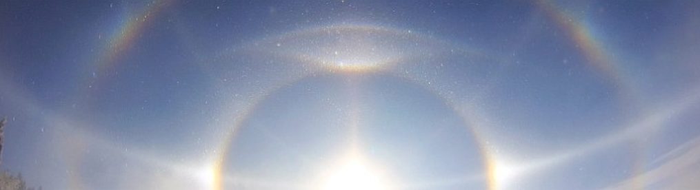
a) view towards the sun, b) view towards the anthelion, c) and d) corresponding simulations using the parameters below

Simulation parameters for HaloPoint 2.0
On the photographs, the following halo species could be identified:
– 22° circular halo
– both 22° parhelia
– upper and lower tangent arcs
– upper and lower light pillar
– upper suncave Parry arc
– circumzenithal arc
– 46° circular halo
– supralateral and infralateral arcs
– both upper Tape arcs
– parhelic circle with blue spot
– 120° parhelia, slightly elongated perpendicular to the parhelic circle
– heliac arc
– subhelic arc
– Wegener anthelic arc
– Hastings anthelic arc
– Tricker anthelic arc
– diffuse anthelic arcs (Greenler and Tränkle)
– diffuse 87° halo (maybe)
There were no detectable contributions from Lowitz arcs, Moilanen and related arcs, or pyramidal halos. From this, the presence of four crystal populations can be inferred:
– random orientations (indicated by the circular 22° and 46° halos)
– plates (22° parhelia, 120° parhelia)
– singly oriented columns (tangent arcs, supralateral and infralateral arc, and many more)
– Parry orientations (Parry arc, Tape arcs, heliac arc)
Note that the circumzenithal arc is not a sufficient indicator for plates, as it can also be produced by Parry crystals, in this case belonging to the group of Tape arcs.
The singly oriented columns were indeed dominating the display. This can be concluded from the observation that the 22° and 120° parhelia appeared not as bright as in other displays, neither does the suncave Parry arc. Tape arcs and the heliac arc present only occasionally, and no antisolar arc was observed.
In the following, some of the rarer effects will be specifically addressed. From some of them, conclusions concerning the crystal shapes can be drawn (i.e. which shapes have to be assumed for a consistent simulation).
Arcs in the vicinity of the anthelion

12:42 CET (unsharp masked)
Apart from the parhelic circle, Wegener anthelic arc and subhelic arc, the loop of the Tricker anthelic arc sticks out quite prominently here. Remarkably, the upper part of the loop is missing in some other photos taken only a couple of minutes before and after the one shown above. Around the anthelion, the diffuse arcs of Greenler and Tränkle can be seen.

a) Tricker anthelic arc, b) Greenler diffuse anthelic arc c) Tränkle diffuse anthelic arc, d) sum of all ray paths through singly oriented columns
The simulations above were calculated using regular hexagonal prisms with a fixed c/a (length/width) ratio of 2. Variations of the cross section towards a trigonal shape and changes of the c/a value do affect these halo species only slightly. The anthelic arcs of Wegener, Greenler and Tränkle are clear indicators for singly oriented column crystals. The parhelic circle, subhelic arc and the Tricker anthelic arc can either stem from columns or Parry crystals, but the dominance of column crystals in this display makes it likely that all the discussed species are due to them.
Note that in the full simulation for column crystals (d), a pronounced blue spot on the parhelic circle is visible. This effect is caused by a dispersive total/non-total transition of the internal reflection at a basal plane along a 3-1-6 ray path (with two 90° wedge angles between the participating planes). A similar effect along the 1-3-2 path with effectively the same geometry exists in plates (see Mika Sillanpää et al. for details and below for further discussion). A suitable name for this lesser known class of effects might be “critical angle (of internal reflection) halos”, in contrast to the familiar minimal deflection halo species.
120° parhelia and colored stripes in their vicinity

12:40 CET (unsharp masked, increased contrast)
The 120° parhelia appear slightly elongated perpendicular to the parhelic circle. Also, from the blue spot a slanted colored streak emerges upward. Longer white arcs through 120° parhelia or subparhelia can be attributed to Lowitz oriented crystals (as in a recent Rovaniemi display). However, here it would not be justified to introduce a further crystal population, especially since there are no traces of other Lowitz arcs. The easiest solution is to increase the random tilts of the plate crystals, which results in pillar-like 120° parhelia. The 22° parhelia are not affected greatly by this, and the parhelic circle keeps its well-defined narrow width, as it is mainly made by columns with small tilts. Also, the elongation of the blue spot off the parhelic circle is matched by the simulation with larger plate tilts, resulting in a superposition of a brighter localized blue spot from columns on the parhelic circle with a streak from tilted plates that corresponds to a short segment of the full “blue circle” which would be expected for random orientations.
The streak appeared with a remarkably high color saturation, as from theory only a pure blue can be expected at best. Very likely the saturation is increased by the processing (unsharp masking), which justifies to treat a simulation image the same way (see below). Unexpected high degrees of coloration have also been noted earlier (Mika Sillanpää et al.).

a) simulation of the right 120° parhelion including all crystal populations (parameters as shown above), b) simulation filtered with unsharp masking, the arrow indicates the colored streak from tilted plates
Variations in the c/a ratio do not effect the simulation results much, but strictly regular hexagonal plates generate rather strong Liljequist parhelia which are not visible in the photos. However, already slight changes in the plates’ cross section shape lead to their disappearance (see Marko Riikonen: Halot, p. 52). On the other hand, one has to be careful with shapes that go too far in the direction of triangles, as then the Kern arc becomes more prominent, and this species was also not detectable in any of the photos. The chosen Gaussian distribution (standard deviation of 0.2, mean shape parameter 1.2) gives a satisfying result by not enhancing either of them.
Wegener/Hastings splitting

a) photograph from 12:55 CET (unsharp masked), arrows mark Hastings (upper) and Wegener (lower) anthelic arc, b) corresponding simulation, using the parameters shown above. At the left edge, the supralateral arc and one of the Tape arcs is visible.
Towards the sunward part of the sky, the anthelic arc of Hastings (made by Parry crystals) splits off from the Wegener arc (made by columns), in accordance with the simulation.
Diffuse 87° halo
The diffuse 87° halo is a critical angle effect similar to the blue spot, but occurring along a 4-6-8 (or 3-5-7) path, i.e. involving two 60° wedges along its course. It always requires some deviation from the regular hexagonal cross section of the prism crystal towards a trigonal shape, i.e. a non-regular hexagonal with two triplets of short and long sides each, while keeping the mutual 120° angles; or in the extreme case a true triangle. In principle, a blue edge should mark the intensity decrease of a brighter disk of 87° in radius around the sun, if made by randomly oriented crystals. However, the diffuse halo from columns turns out to be more pronounced, and keeps the 87° angular distance only straight upwards above the sun, where it is usually observed. It occurs more often in lamplight displays, with only two documented cases against a blue daylight sky as of now (here and here).

12:56 CET (unsharp masked and size of bright pixels increased)
The trouble with identifying it here is that it nearly coincides with the upper loop of the heliac arc (distance from the sun to the loop top = 120° – 2 · sun elevation), and both species tend to have a grainy glittering appearance in diamond dust. The difference between them is though, that the heliac arc should be a white stripe of a certain limited width, while the diffuse halo marks only an intensity step from a brighter to a darker region. The approximate positions of both species are indicated in both the photograph and simulation below.

Locations of the heliac arc (green) and diffuse 87° halo (red) in the photograph (a) and simulation (b). The arrow marks the position of the (rather weak) 87° halo in the simulation.
As seen, the heliac arc should retract further towards the sun for lower elevations as the actual glittering edge does. In a single frame as shown here, the heliac arc can barely be traced, but when flickering through the available seven photographs of this celestial region, there seems indeed to be a stripe of more intense glitter following the green line embedded in the brighter disk (note that the pictures were taken without a tripod and their combination to a stack image would therefore be complicated). This implies that the remaining outer rim of the glittering, marked in red, should indeed be the 87° halo. Of course there are only few reference cases for comparison, hence this identification in not fully sure.
In the simulation it is not possible to set all column cross sections to triangles, as this would extinguish their blue spot on the parhelic circle, which is needed to match the 120° parhelia region (the critical angle effects, blue spot and 87° halo, are somewhat competitive). As a compromise, I chose a broad distribution between hexagonal and trigonal shapes, so that both blue edge halos from columns are present in the final result.
Author: Dr. Alexander Haußmann, Faculty of Physics, Technical University Dresden, Germany